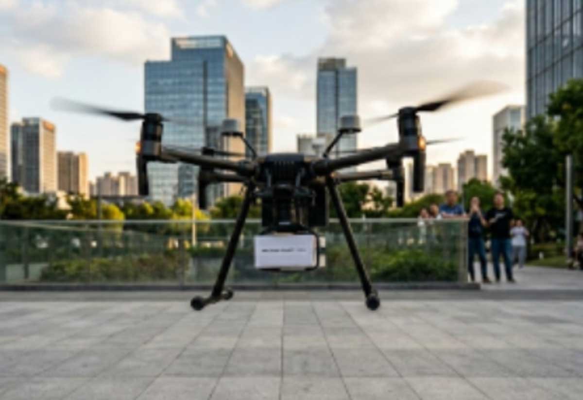
In UAV flight operations, the landing phase accounts for a high percentage of incidents due to the minimal margin for error in environmental variables.
Drone landing is a dynamic process highly dependent on real-time closed-loop feedback. During this stage, the Flight Control Unit (FCU) requires high-precision data for Altitude Above Ground Level (AGL) and vertical velocity.
Any inaccuracies, signal fluctuations, or data latency from the sensors will lead to erroneous calculations of the moment of impact, resulting in airframe bouncing, tip-overs, or hard landings. The performance limitations of the sensing hardware are the primary cause of drone landing failures.
Constraints of Conventional Sensors in Near-Ground Environments
In complex proximity-to-ground scenarios, standard sensing technologies frequently encounter performance degradation due to the inherent limitations of their underlying detection principles.
1. Optical Sensors
Visual positioning systems (monocular or stereo) rely heavily on the extraction and matching of environmental feature points.
- Illumination Sensitivity: In low-light environments, twilight, or high-contrast shadow zones, insufficient illumination or contrast can cause feature points to vanish, rendering the sensor ineffective.
- Surface Texture Requirements: When operating over calm water, thick snow, uniform monochromatic tiling, or specular reflective materials, the system fails to calculate displacement through image differentiation, often triggering localization drift.
2. Ultrasonic Sensors
Ultrasonic ranging hinges on sound wave reflection but faces significant physical limitations during final descent.
- Signal Scattering & SNR: Ultrasound has a wide beam angle (20°–60°). At close range, reflections from irregular surfaces become diffuse, and near-ground clutter causes the signal-to-noise ratio (SNR) to drop sharply.
- Acoustic Absorption: When landing on dense grass, carpet, or soft soil, sound waves are absorbed rather than reflected. The resulting lack of echo leads to false “high altitude” readings.
- Specular Reflection and Angular Loss: If the landing surface is inclined, the ultrasonic pulse reflects away from the receiver along the angle of incidence instead of returning vertically, resulting in a total loss of ranging data.
3. Barometers
Barometers estimate altitude via atmospheric pressure, which is highly vulnerable to thermal drift. More critically, as a drone nears the surface, the powerful downwash from the rotors creates localized pressure turbulence. This phenomenon induces errors typically ranging from 10 cm to over 30 cm.
4. GNSS
The vertical positioning accuracy of GNSS is inherently inferior to horizontal precision. During landings near structures or dense vegetation, multipath interference can cause sudden vertical position errors ranging from tens of centimeters to over one meter.
5. Infrared Sensor
Infrared sensors are susceptible to interference from ambient light and surface characteristics. Direct sunlight can saturate the receiver, causing signal spikes and unstable readings.
Additionally, black or low-reflectivity objects tend to absorb infrared light rather than reflect it, which significantly reduces the sensing range and can lead to detection failures.
Advantages of Benewake LiDAR for Drone Landing
Taking the Benewake TFA300 Series sing-point LiDAR as an example, we can define the practical performance boundaries of LiDAR in drone landing scenarios.
1. Environmental Adaptability
The TFA300 Series operates reliably under intense ambient lighting of up to 100,000 Lux, with a detection range spanning 0.1m to 290m (at 90% reflectivity). It maintains measurement continuity despite adverse outdoor conditions such as rain, fog, or dust.
2. Precision and Resolution
The TFA300 delivers a ±10 cm range accuracy and a 1 cm distance resolution, with a repeatability error of less than 3 cm (1σ). Compared to GNSS vertical errors, which frequently fluctuate between 20 and 50 cm, drone LiDAR sensors offer a far more dependable absolute altitude reference.
3. Refresh Rate
This is the most critical metric for the TFA300. The series features a default operating frequency range of 1 Hz to 1,000 Hz, with the option to increase to 10,000 Hz in ultra-high frequency mode.
For near-ground deceleration control, this allows the flight control system to capture minute altitude changes within extremely tight time windows, eliminating response lag caused by data latency.
4. Weight and Connectivity
The TFA300-L (frame-only version) weighs a mere 10.5 grams. It utilizes a standard JST GH interface supporting both UART and CAN protocols, enabling seamless integration into mainstream flight control ecosystems.
5. Field Proven Reliability
To date, TFA300 has supported delivery drone customers in completing over 400,000 accident-free package drops worldwide. This figure represents the continuous validation of Benewake LiDAR performance in diverse, real-world landing environments.
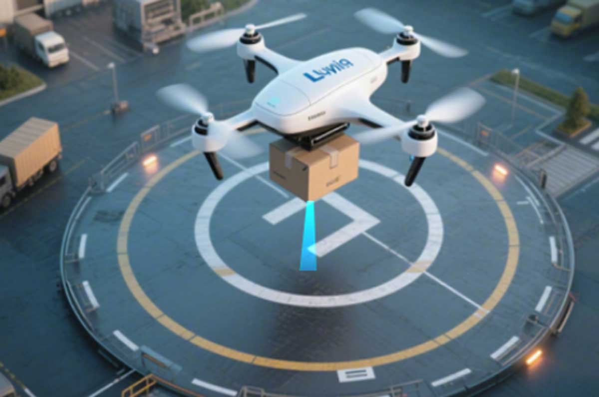
Safe Drone Landing Workflow via Advanced LiDAR
1. High-Altitude Assistance (10m–2m): Sensor Calibration and Fusion
The flight controller uses the LiDAR absolute altitude for the drone as ground truth to correct barometric drift in real time.
The LiDAR sensor continuously acquires real-time altitude readings during the initial descent, establishing a stable and accurate altitude baseline for the subsequent deceleration phase.
2. Proximity Deceleration (2m–0.5m): Smooth Vertical Velocity Control
This is the highest-risk segment of the descent. The aircraft must decelerate continuously while avoiding an excessive descent rate that could lead to a hard landing.
Utilizing high-frequency distance data from the LiDAR sensor, the flight control system(FCS) calculates the exact vertical velocity relative to the ground. The system then compares the measured speed to a preset target deceleration curve, dynamically adjusting the motor RPM to ensure the UAV reaches the touchdown point at near-zero velocity.
3. Touchdown Decision (0.5m–0m): Motor Cut-off Determination
Many incidents occur at the exact moment of impact. Premature motor shutdown results in an uncontrolled free-fall from residual altitude, causing structural damage upon impact, while delayed shutdown can trigger ground-effect interference and airframe bouncing, leading to tip-overs.
The LiDAR monitors the rate of altitude change. When the altitude remains constant over a micro-window and the calculated vertical velocity approaches zero, the system confirms physical contact and commands the motors to power down.
4. Landing on Complex Slopes and Uneven Terrain
In search-and-rescue or power-line inspections, drone landing zones are rarely perfect planes. If a flight controller fails to perceive a slope, one landing gear leg may strike the ground while others remain suspended, causing a shift in the center of gravity and a subsequent tip-over.
UAVs equipped with Benewake LiDAR utilize precise downward ranging combined with IMU attitude data (pitch and roll) to calculate the relative ground inclination. The FCS performs final-moment attitude adjustments to ensure all landing gear legs contact the surface as simultaneously as possible, distributing the impact force and suppressing tip-over risks.
Conclusion
Drone landing failures are not merely a matter of flight controller tuning; they are fundamentally rooted in the physical limitations of conventional sensors in near-ground environments.
Benewake LiDAR, exemplified by the TFA300 Series, addresses these limitations through high-frequency, high-precision, and environment-robust altitude measurement. For UAV manufacturers and solution integrators, upgrading to LiDAR-based altimetry is a proven path to reducing landing incidents and improving operational reliability.


